
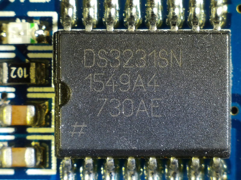
The DS3231 Real Time Clock (RTC) breakout keeps extremely accurate time, has a battery backup, and only costs a few dollars. Combine it with just about any microcontroller, a display, plus a simple stand, and you have a custom precision clock that can sit on your desk and satisfy your timing needs in a visually-unique way.
I work in a global 24×7 manufacturing environment. Many global companies choose to use Universal Coordinated Time (UTC) because it provides a common standard reference across the fleet and avoids the problems associated with daylight savings time. (And yes, I know it should be abbreviated “UCT” based on what it stands for, but you’ll have to blame the French for that one.)
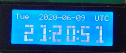
Since I end up doing a fair amount of validation and troubleshooting based on UTC data, I thought it would be handy to have a clock on my desk dedicated to displaying the current UTC date and time. Since I happened to have some ATMega328P chips and 20 character I2C LCDs lying around, I thought it would be fun to whip up a simple little clock with an easy-to-read display.
If UTC doesn’t interest you, you can easily change this to be whatever time zone you prefer.
Parts Needed
There are two main ways to approach this project. One is to use an Arduino development board. Pretty much any model will work. The other option – the one I ended up using – is the ‘naked’ processor approach. The additional components needed for this approach are pretty minimal:
- ATMega238P
- 16MHz crystal oscillator
- (2) 22pF ceramic capacitors
- 10nF ceramic capacitor
- 6mm momentary button (reset)
- 10k 1/4 watt resistor
- Micro USB to breadboard breakout
- 10uF electrolytic capacitor
- Half-size breadboard or proto board
Additional Parts Needed (for either option)
- 20×4 Character LCD screen with I2C backpack
- DS3231 RTC breakout
- CR2032 battery (for the DS3231)
- (2) Momentary buttons (or 3 if you want to implement an alarm)
- USB cable
- 5V 1A DC converter with USB jack
- Case or stand
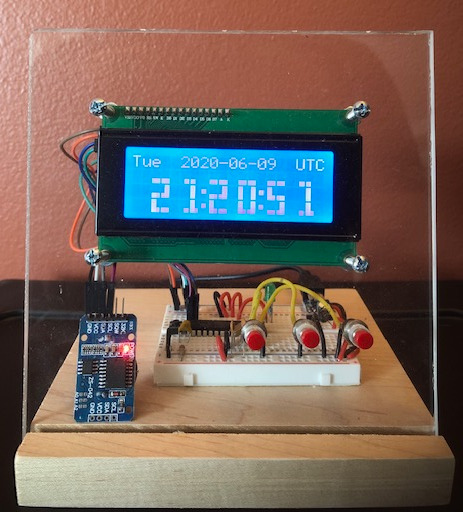
I opted for a very simple stand made of 3/4″ think hardwood base and 1/4″ clear acrylic. Both are about 5 1/2″ square. The slot in the base for the acrylic was cut using a table saw angled about 10 degrees back from vertical.
Wiring
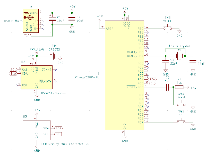
Refer to the ATMega328P pinout (28-pin dual inline package)
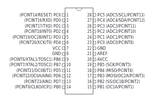
Since the LCD and RTC both use I2C, just connect both of their SCL pins to SCL on the Uno or physical pin 28 on the 328. SDA pins go to SDA on the Uno or physical pin 27 on the bare chip.
Buttons and 328 Pin #s:
– VALUE button: 12
– SET button: 13
– ALARM: 14
Other lead of each button is connected to GND.
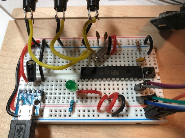
Once hooked up, the board should look something like this. Extra green LED and current-limiting resistor is optional (and not shown in the schematic.)
Programming the ATmega328P
If you’re using an Arduino dev board, you can just copy the sketch from the GitHub repo and flash it to your board:
https://github.com/DigiTorus86/two-bit-tinker/tree/master/Arduino/Uno/rtc-lcd-utc-clock
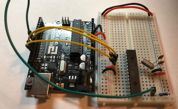
If you’re going naked, then it’s a little more work to flash the bootloader and sketch to the microcontroller. If your ATmega328 didn’t come with the bootloader installed, then you’ll need an Uno board to serve as the in-series programmer.
Bootloader Process
- In the Arduino IDE, go to Load File -> Examples -> 11. ArduinoISP
- Select the Board and Port as usual and then upload the sketch to the Uno board.
- Select: Tools -> Board -> Arduino Nano
- Select: Tools -> Processor -> ATmega328P
- Select: Tools -> Programmer -> Arduino as ISP
- Select: Tools -> Burn bootloader
- You should see a “Done burning bootloader” message if successful.
Now your micro is ready for the sketch to be flashed. There are a couple ways to do this, but the simplest is to just flash the 328 in the Uno, then swap it out with the one you just put the bootloader on. If you go this route, you’ll want to use an IC puller and be very careful to avoid wrecking the pins on the chip.
Once everything is setup and flashed, it’s time to power up the board. The day and time should be displayed right away. If the LCD backlight does not come on, make sure that the 2 LED pins are shorted together. You may also need to use a small screwdriver to adjust the contrast trim pot on the back. (Be gentle!)
To set the correct date and time, push the SET button. The day of the week should start blinking. Use the Value button to change the value of the blinking item. Then press SET to move on to the next date/time element, and change the values as needed. Finally, when the seconds are blinking and the SET button is pressed, the new date/time value is written to the DS3231. This means that as long as you have a good CR2032 battery in place, it will maintain the settings even when the clock loses power.
Conclusion
I made this clock several years ago, and it has worked remarkably well. The DS3231 keeps very accurate time. I have not needed to replace the battery yet. There have been one or two times when I’ve come in to work and the display has been scrambled and needed a simple reset. Other than that, it’s been flawless – and has been a nice conversation starter to boot.
The DS3231 also has address space for an alarm value and a pin that can output a square wave that could be used to drive a small speaker. I had considered adding an alarm feature, but never really found the need for it with this clock. I did, however, add an alarm to a more advanced clock project, which will be featured in a coming post.
Comment (1) on "Naked UTC Time Clock"
Comments are closed.