
A waveform generator is a handy little tool for stimulating and testing electronic components and assemblies. Any work with filters, amplifiers, or other frequency-sensitive designs can benefit from the insights gained through a controlled signal input. Here’s how to make one for about $30.
Bill of Materials
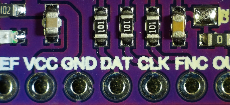
- AD9833 waveform generator IC or breakout board
- I2C OLED display, 128×64 pixels
- (2) rotary encoders
- Arduino Uno / ATmega328P, or other similar microcontroller
- 5V power supply with suitable filtering
- Casing and wiring/connectors
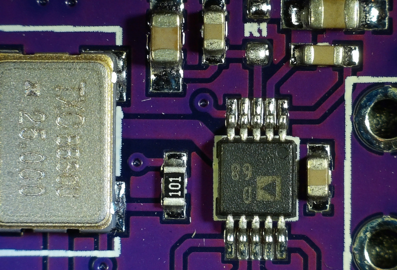
The heart of the system is the AD9833 Low Power Programmable Waveform Generator. It can generate sine, triangle, and square waveforms up to 12.5MHz. Full datasheet is available on the Analog Devices website here:
https://www.analog.com/media/en/technical-documentation/data-sheets/ad9833.pdf
For the “head”, the design uses the trusty ATmega328P microcontroller. Since the MCU just provides the configuration instructions to the actual waveform generator rather than generating them itself, the modest capabilities of the ATmega328P are not a constraint. Setup and usage are similar to the Naked UTC Time Clock project.
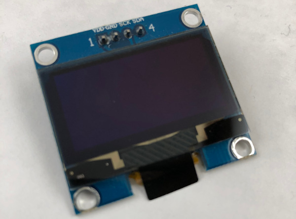
The display is an SH1106 1.3″ 128×64 pixel OLED using I2C. Any similar I2C OLED should work fine, but the larger screen size of this model comes in handy.
You might be thinking that a bigger 320×240 TFT would look nicer – and you’d be right. However, there are a couple reasons to choose the OLED instead. The first is that the AD9833 uses SPI for receiving it’s configuration data. However, unlike most SPI displays (which normally use SPI Mode 0), it uses SPI Mode 2. This means that the clock signal polarity (CPOL) is inverted, going from high to low on the leading edge.
Many displays and display drivers don’t share the SPI bus nicely with devices that use other SPI modes. Getting a specific driver chip can be problematic, so it’s much simpler to just use an I2C display instead and avoid the whole issue.
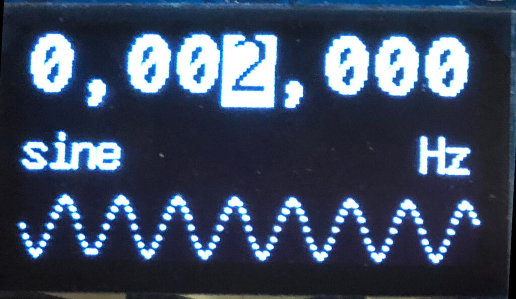
Also, there’s not that much information to display, so the limited resolution of the OLED display is not a problem and allows for a slightly more compact build.
Finally, a pair of standard rotary encoders + switches are used to adjust the frequency, select the waveform, and enable/disable output.
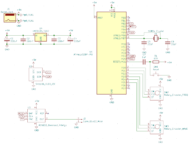
Schematic in PDF format:
https://github.com/DigiTorus86/two-bit-tinker/tree/master/documents
Coding
For the sketch, three different libraries handle the main peripheral interfaces for the OLED display, wave generator, and rotary encoders.
The U8G2 library from Oliver handles the SH1106 OLED display. You may need to play with the constructor a bit depending on the manufacturer of the display you use. https://github.com/olikraus/u8g2
One nuance with U8G2 is that you want to put all of your screen drawing code into a common do-while loop that begins with firstPage() and executes until nextPage() returns false. This is to conserve RAM usage compared to a full frame buffer.
The AD9833 Library by Bill Williams has a nice, clean interface for controlling the waveform generator.
https://github.com/Billwilliams1952/AD9833-Library-Arduino
For the rotary encoders, the Rotary library from Brian Low was used.
https://github.com/brianlow/Rotary
Source code for the sketch can be found at:
https://github.com/DigiTorus86/two-bit-tinker/tree/master/Arduino/Uno/uno-waveform-ad9833-sh1106
Testing
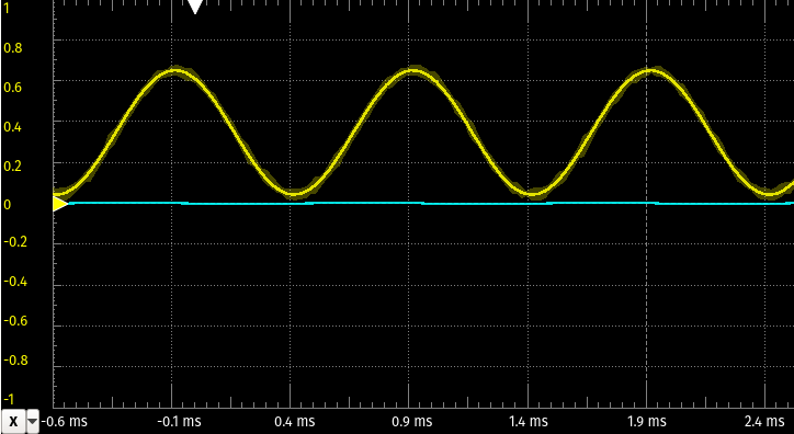
Here’s how the waveforms measured out. From the datasheet, we see that the expected DAC output voltage is 0.65V, and that’s what’s reflected in the signal trace:
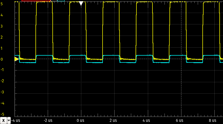
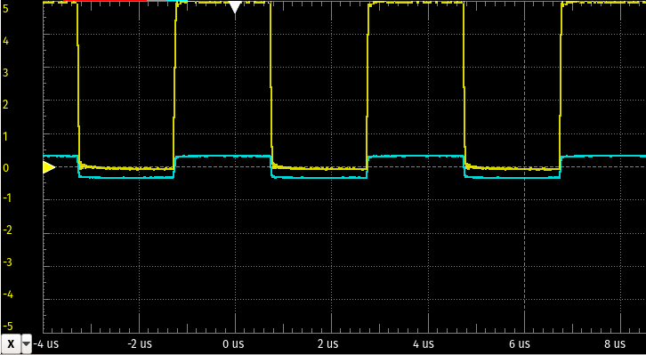
With the square wave, you’ll see that instead of 0 – 0.65V, the output is up to 5V:
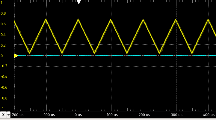
A half square wave has twice the period at the same frequency as the square wave:
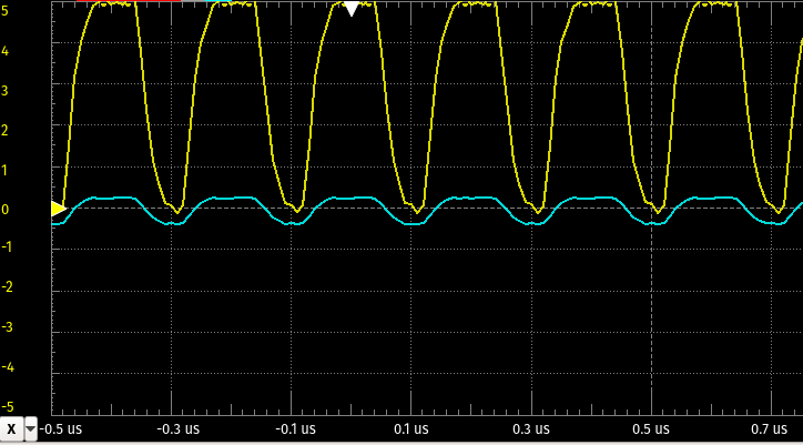
At 5MHz, the squareness suffers a bit, but that’s probably as much or more due to my test setup and leads as opposed to the chip output. However, if you’re playing in the MHz signal range a lot, you’re probably going to want a more sophisticated setup anyway.
The “case work” is still pending and waiting on a couple parts but should be completed soon.
Source code:
https://github.com/DigiTorus86/two-bit-tinker/tree/master/Arduino/Uno/uno-waveform-ad9833-sh1106
Comment (1) on "AD9833 Waveform Generator"
Comments are closed.