
The Roland SCC-1 GS sound card was a great piece of kit back in the day, with 24-note polyphony, excellent wave table samples, and high-quality onboard reverb and chorus effects. Released in the early 90’s, it cost almost $500 USD (~ $1,000 in 2022 inflato-bucks) depending on what was bundled with it. However, that extravagant expenditure allowed you to escape the limitations of the FM-synthesized MIDI voices that were provided by the Sound Blaster sound cards of the time.
Time and technology march on. While the audio capabilities of the SCC-1 have aged well, the 8-bit ISA bus that it used did not. This rendered the SCC-1 practically unusable with most computers sold in the last 20+ years.
The good news is that the SCC-1 is mostly just a card version of the SC-55 Sound Canvas and is not heavily-dependent on the ISA bus for control. It really just needs a a few hundred milliamps of +5V and +12V DC power. All of the card functions are controllable via the MIDI IN port using standard control and sysex messages.
For just a few dollars and an hour or two of your time you can resurrect this antique card, and be on your way to making beautiful music with it.
Connecting the Board
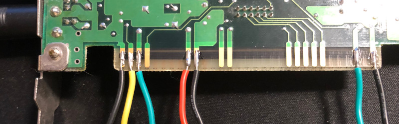
Using some short lengths of hookup wire, solder the pins as shown. The big archaic ISA connector strips are just about the easiest thing you’re ever going to solder. The needed wires/pins are all on the B (solder) side. In order from the rear of the card towards the front, they are:
GND (black)
RESET (yellow)
+5V (green)
NC
+12V (red)
GND (black)
NC (next 7 pins)
+5V (green)
GND (black)
Powering the SCC-1
The official power consumption of the SCC-1 is 200 mA for +5V and 20 mA for +12V. There are a number of different ways to supply this current. An AC-DC power supply such as the Mean Well RT65B which outputs +5V, +12V, and -12V will work nicely. While this supply is overkill for the modest needs of the SCC-1, it also makes a great Eurorack power supply.
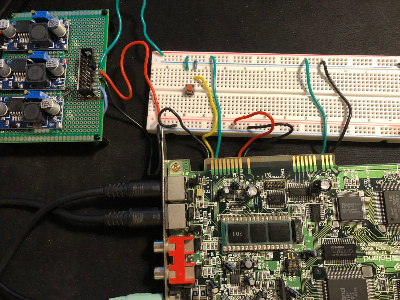
The power supply shown here uses an old laptop brick, which outputs 2.4A at 19V. A pair of LM2596 switching power supplies provide the +5V and +12V output needed by the SCC-1. The third LM2596 in the picture generates a -12V rail, which is not used in this project.
The RESET DRV pin needs to be tied to GND using a 1K resistor. After power on, this pin needs to be momentarily connected to +5V in order for the SCC-1 to respond to input.
You can remove the IRQ jumper – you won’t need it.
Testing
The SCC-1 uses mini-DIN connectors for the MIDI IN and OUT connections. If you don’t have the ones that originally came with the unit, you’ll need to pick up a pair of adapter cables. Insert the MIDI IN connector and attach it to the MIDI OUT from a keyboard or other MIDI device. Insert a headphone or powered-speaker plug, and power everything up. Press the reset switch, tickle the ivories on your keyboard, and you should be rewarded with the classic Roland piano samples.
Using the SCC-1
If you don’t have a hard copy of the original owner’s manual, you’ll want to download the PDF. It did not appear to be available on the Roland site, but I was able to find it here:
https://usermanual.wiki/Document/scc1om.1736588447/view
The manual lists all of the program tones/samples, drum kits, and parameter settings. You’ll want to refer to it when setting up patches for the SCC-1.
While the breadboarded setup shown here is certainly functional, a better arrangement would include a case with either a power jack or an enclosed power supply and switch. If you end up doing this, please post in the comments below!