
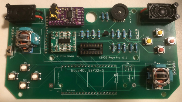
Directions for assembling and testing the ESP32 R4ge Pro development kit. For more background on this board, please see the previous post.
Preparation
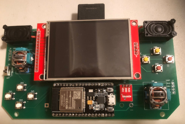
Before you start, make sure that you have all the required parts available and none of them are dirty or damaged. Dealing with issues that you spot up front is usually easier. Any dirt or grease can be cleaned up with a bit of isopropyl alcohol and a clean rag.
Download the GitHub repo from https://github.com/DigiTorus86/ESP32-R4ge-Pro and refer to the schematic and BOM list in the documents folder.
A bit of painter’s tape is helpful for holding some of the larger components in place while you solder them. If you need a primer or refresher on soldering, Adafruit has a number of good resources, including this video: https://learn.adafruit.com/collins-lab-soldering
Assembly Order
The general rule of thumb is to start with the components with the lowest profile and work your way up to the bigger/taller ones. The following is the suggested order of assembly:
- Resistors
- Buttons
- Rotary potentiometer
- IC socket
- Power switch
- PAM8403 breakout
- PCM5102a DAC breakout
- Microphone
- Transistor
- Speakers
- Joysticks
- Female header pins
- Insert IC into the 16-pin socket
- Insert the ESP32 and TFT
- Verify operation using USB on ESP32
- Battery charger
- Battery holder
- Verify operation using USB on battery charger
- Charge battery and verify operation using battery power
This is by no means the only order that will work, so feel free to modify. However, you should definitely perform the verification step BEFORE soldering the battery charger and holder.
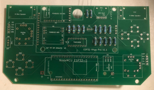
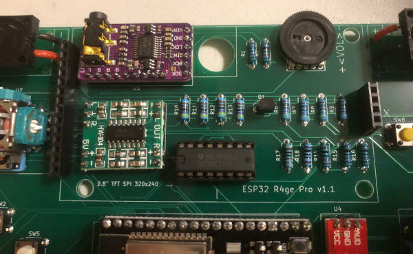
Step 1 – Resistors
The orientation of the resistors is not critical, but it is easier to verify that you have them in the proper location if they all are oriented the same way (i.e. with the tolerance band towards the lower edge of the board.)
Step 2 – Volume, IC Socket, Buttons, and Power Switch
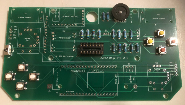
The pins on the rotary pot are easy to bend, so they may need a bit of adjustment to line up with the mounting holes. Make sure to solder both the electrical pins and the two additional mounting pins.
The IC socket is not required, but strongly recommended. Make sure the notch points to the left edge of the board.
Step 3 – PAM8403, PCM5102a, Transistor
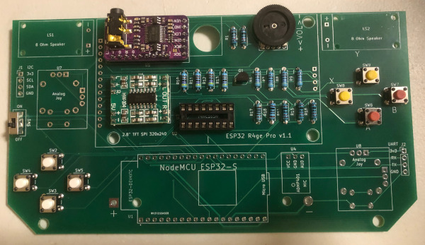
For the breakout boards, separate the male header pins needed for each board, place them in the PCB, then seat the breakout board over the top of them. Solder the short ends of the pins to the breakout board, then solder the pins to the PCB.
For the transistor, be sure to match the flat side of the transistor case to the flat side printed on the PCB outline (flat side towards bottom edge.)
Step 4 – Speakers and Joysticks
Cut four 3cm wires for the speakers. Strip off about 1/2 cm of the insulation from one end for attaching to the speaker. Leave about 1cm of insulation, and strip the rest for insertion into the PCB. Having a little extra on the PCB end just helps keep it in place a bit easier.
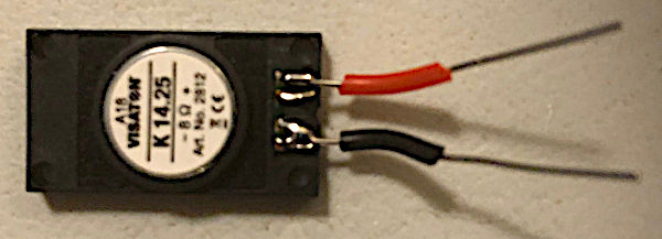
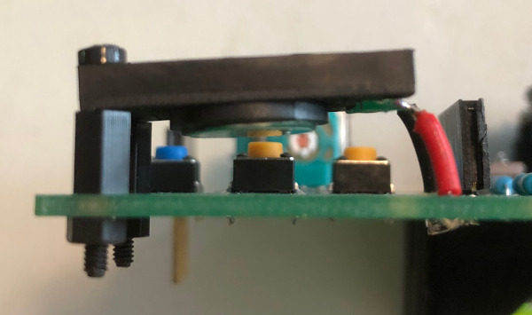
Attach the speaker standoffs to the PCB using the nut on the bottom. Solder the short ends to the speaker terminals. Gently bend the wire to approximately 90 degrees as close to the edge of the speaker as possible. Insert the long ends into the PCB and use the screws to attach the speaker to the standoffs. Finally, solder the speaker wires to the PCB.
The joysticks have a lot of pins and may take a little finessing to get them all seated in the PCB. A small right-angle pick is really handy to help with this, or a small screwdriver will do the trick too.
Step 5 – Microphone and Female Headers

Cut the female pins for the ESP32 and mate them to the ESP32. Then seat the female pins into the PCB. Flip over and solder.
Cut the male and female headers for the TFT and mate them, placing the female ends into the PCB and seating the TFT over the short male pins. Solder the TFT to the male pins, then flip over and solder the female pins to the PCB.
Step 6 – Insert Removable Components
Seat the 74HC165 into the IC socket. You’ll probably need to bend the pins a bit narrower for it to fit. Verify the IC orientation before seating, with the notch pointing to the left. Don’t use any significant pressure until you’re sure that the pins are all in the correct position inside the socket.
Step 7 – Verify Operation
Before soldering the battery holder or the charger, you should verify operation of the board. The battery holder and charger are both mounted on the back and will cover some of the solder points of other components. If any of these need rework, you would have to de-solder the component on the back first – so its much better to test first.
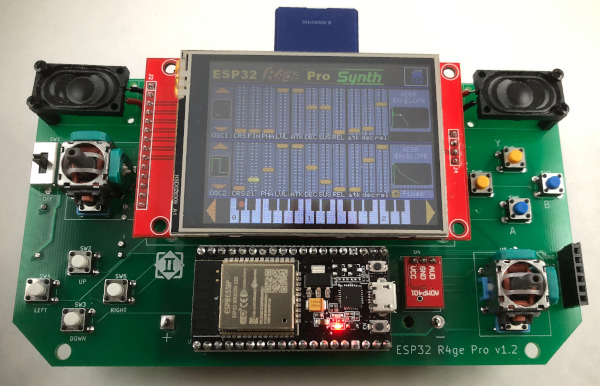
Clone the GitHub repo at https://github.com/DigiTorus86/ESP32-R4ge-Pro. Attach a micro-USB cable to the ESP32 and your computer. Open the esp32-r4ge-pro-test1 sketch and flash it to the ESP32. You should see a screen like this appear:
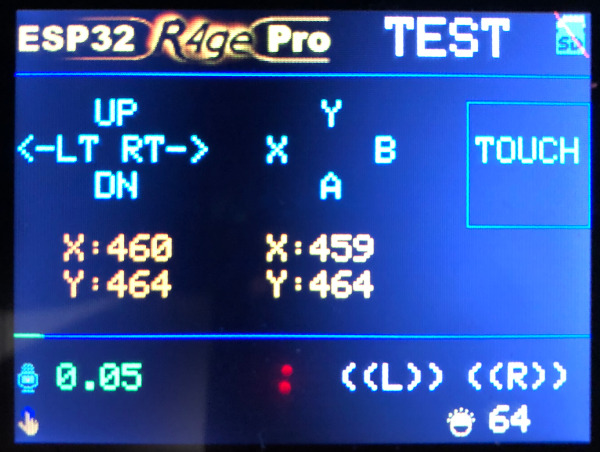
- Push all buttons. The corresponding button on the display should highlight.
- Move the joysticks around. X and Y should change between 0 and 1023.
- Press and hold the [Down] button. The screen should dim.
- Press and hold the [Up] button. The screen should get brighter.
- Turn the volume pot to the middle of it’s range. Press the left button. A tone should play from the left speaker. Press the right button, and a tone should come from the right speaker.
- Touch the [Touch] button with your finger or a stylus. The button should highlight.
- Talk, whistle, or yell into the microphone. The numeric microphone readout should change and the highlighting on the bottom line should get longer as the sound gets louder.
- If you have an SD card, insert it into the holder on the TFT and restart the ESP32. The SD icon in the upper right should NOT have a red diagonal line through it if the card was detected.
If all these tests pass – congratulations! Move on to soldering the battery holder and charger. If a test doesn’t pass, chances are good that one of your solder joints is bad. Examine them closely and touch up any joints that look suspect with a soldering iron. Refer to the schematic to determine which components are in the signal path of the feature that is non-functional.
Step 8 – Battery Holder and Charger
Unplug the cable from the ESP32. Mount the charger on the back of the board, and solder it on the front using male header pins. As with the other breakout boards, it generally works best to solder the breakout board first and then flip over and it solder it to the PCB.
Mount the battery holder on the back of the board and solder it on the front. Make sure you have the polarity correct! Also, be generous with the solder, because inserting and removing batteries places a fair amount of stress on the joint.
Step – Final Test
Insert the micro-USB cable to the charger and your computer or a 5V DC power source. Move the switch to the bottom CHG position. The board should turn on and display the test application. If it doesn’t, immediately check the ESP32 and other components for excess heat. If anything is hot, IMMEDIATELY unplug the cable or you may see the “magic smoke” of a destroyed component.
Insert a CR18650 battery into the holder, paying attention to the polarity. The light on the charger should show red initially. After a while, the light should turn blue, indicating that the battery is fully charged. At that point, unplug the USB cable and move the power switch to the middle BAT position, the ESP32 should turn on and operate normally.
If everything seems OK, but the screen doesn’t come on, you may need to press the EN button on the ESP32 to reboot it.
Congratulations! You’ve verified all functionality and can be confident that you have a fully-operational ESP32 R4ge Pro in your hands. Load up and play around with the other sketches, or develop your own awesome app. Enjoy!