
The EspoTek Labrador is billed as an all-in-one oscilloscope, signal generator, power supply, logic analyzer, and multimeter. How does this tiny $29 USD board measure up? Let’s find out!
The Labrador is an open source hardware and software package created by Christopher Paul Esposito (hence the EspoTek name). It’s powered by an ATmega32A4U microcontroller with 32K of flash and 4K of SRAM. The functional specs as billed are:
- Oscilloscope (2 channel, 750ksps)
- Arbitrary Waveform Generator (2 channel, 1MSPS per channel)
- Power Supply (4.5 to 12V, 0.75W max output, with closed-loop feedback)
- Logic Analyzer (2 channel, 3MSPS per channel, with serial decoding)
- Multimeter (V/I/R/C)
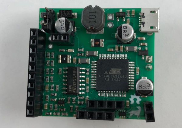
The board itself is a very compact 35x37mm. That compactness comes with a minor drawback – namely that there are no pin labels anywhere on the board. There is a nice pinout diagram on the GitHub docs, but for quick reference having something on the board would be handy. Of course, that would mean a larger board and higher production costs too.
The control software comes in multiple host flavors: Windows, Mac, Linux, RasPi/Debian, and Android. I used the Debian installation on my Ubuntu system, and it installed and started up without a hitch.
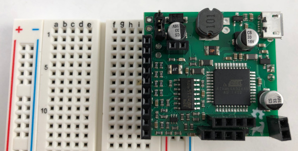
The Labrador connects via a micro USB socket to your system, but also has stacking header pins to allow it to fit on a breadboard. In this configuration, the digital and signal generator pins get their own row, and the power supply positive and ground pins fit into the breadboard power supply rails. The fit was a bit off for my breadboard, requiring the power pins to be bent forward and a lot of jiggling before everything would mount correctly.
Once the board is mounted and connected to your host device via the micro USB cable, you need to calibrate the system. The software will prompt you to do this on startup, but you can also perform this from the main menu.
Calibration involves putting wires in the oscilloscope channel 1 and 2 DC headers. You then touch them to the USB connector case to get a ground reference. Then you connect the Ch1 wire to the power supply positive voltage pin/rail. If everything completes successfully, you’re good to go. If not, you’ll be shown a message showing what went wrong and you can try again.
Oscilloscope
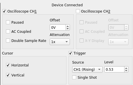
The oscilloscope widget controls the basic settings, and mouse/keyboard controls handle the pan/zoom/cursor functions.
To test the o-scope, I hooked it up to the output of the AD9833 Waveform Generator that was covered in the previous post. The output window showed a nice, steady 1kHz-ish sine wave at 0 – 0.65V, as expected.
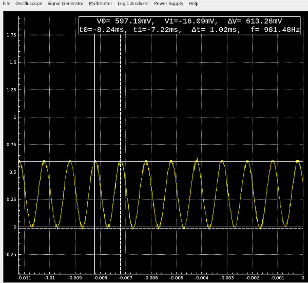
The cursor measurement function works well. To measure amplitude, left click on the bottom of the waveform, then drag to the top of the waveform and release. For horizontal axis time/frequency measurements, do the same starting with a right mouse click.
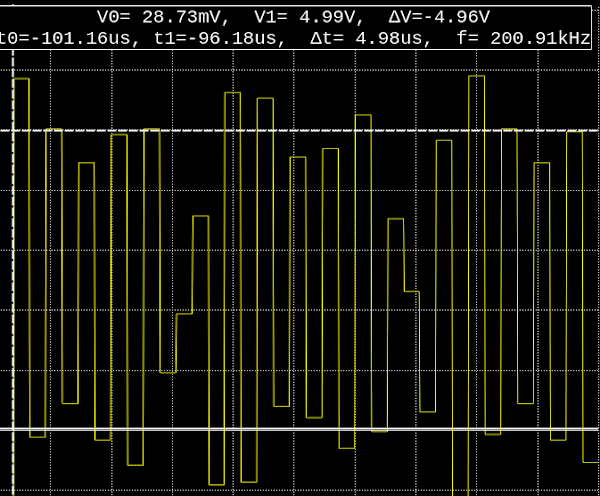
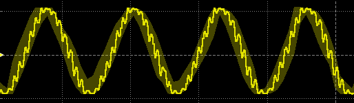
Overall, the o-scope functions performed admirably within typical audio sampling ranges. Around 50 kHz, the bit resolution starts noticeably degrading, and at 100 kHz it looks more like a game of Tetris than a sine wave.
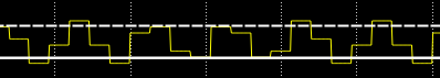
This isn’t a criticism of the board. It’s simply the limitation of having a 750ksps rate. Square waves are simpler to sample/have less contour information, and were usable up to about 200 kHz , though the amplitude measurements seemed to suffer a bit.
Signal Generator
The signal generator widget controls the standard parameters for up to 2 simultaneous waveform outputs.
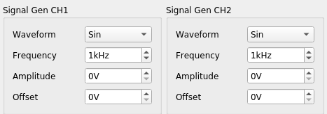
The maximum frequency is 62.5 kHz. This is significantly lower than the 10MHz top end of the AD9833 project, but sufficient for many common testing scenarios such as PWM, audio filter response, and op amp output.
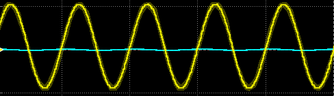
To verify the Labrador’s signal output, I hooked it up to my Digilent Analog Discovery2. It’s also a USB-controlled multi-function device, but with over 100x the sampling power (and over 10x the cost) of the Labrador. The generated 1 kHz sine wave looked smooth and steady:
Around 40 kHz, things start looking a bit ragged, but are still pretty usable:
Logic Analyzer
The 2-channel logic analyzer lets you configure the serial connection properties and display hex value conversions for the signals it observes.
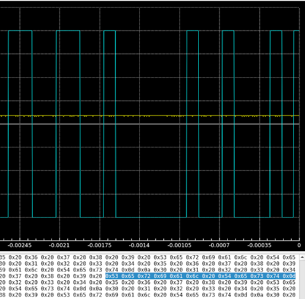
To test this out, I loaded an ESP32 with a simple sketch that wrote some data out to the Serial2 port, and hooked the TX2 pin to the Labrador’s Ch1 logic analyzer pin. The sketch output was “Serial Test”, CR-LF, and then 0-9 separated by space characters. This was reflected as expected in the hex view:
For I2C, I hooked Ch1 to SDA and Ch2 to SCK on an I2C OLED screen driven by an ATmega328P. The Labrador captured the signal changes just fine, but no additional I2C signal information was displayed.
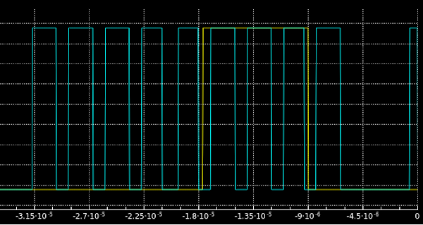
Adding a hex readout of the I2C values and events (address, read, write, restart, ACK, NAK, etc.) would be my top vote for a new feature request.
Multimeter
The multimeter function is simple to use, but the measurements appeared to be significantly off compared to several different digital multimeter, power supply, and known voltage measurements. Example results:
DMM showed 4.7V, Labrador showed 3.5V
DMM showed 9.2V, Labrador showed 7.95V
PSU showed 4.9V, Labrador showed 3.55V
It’s possible that this was the result of an error during calibration, but I did re-calibrate multiple times with similar outcomes.
Bottom Line
What the Labrador provides in a tiny package for less than $30 is very impressive. If you work primarily with low-voltage, low-frequency signals or want something you can easily throw in your laptop bag for some light-duty field work, the Labrador is a wonderful bargain. It would also be useful for students and hobbyists looking for a low-cost way to diagnose and generate some signals.
The included software is user-friendly, works on most of the major platforms, and provides the key functionality that most people will use. And if it’s missing a feature you *really* want, you can always download the source and add it yourself if you’re so inclined.
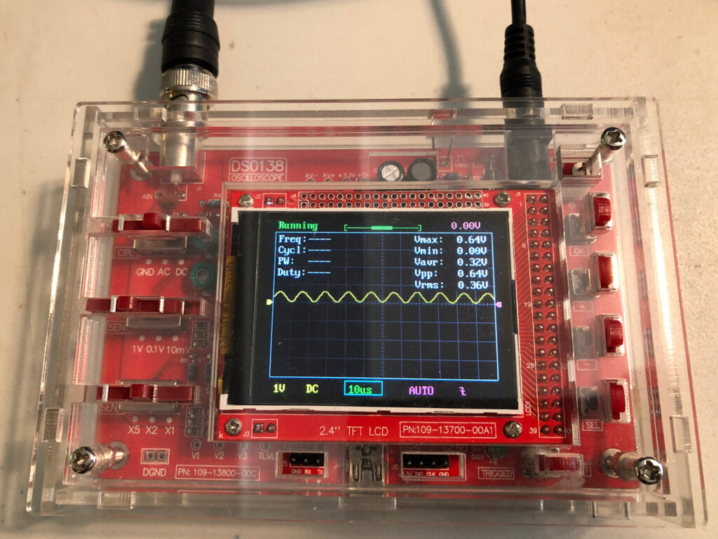
Will it take the place of an Analog Discovery2 or a dedicated bench scope? Nope. A better comparison would be between the Labrador and a DSO138 oscilloscope/kit. The performance of both scopes are fairly similar, but the Labrador has a much more useful interface and many more features. I’d only go with the DSO138 if I really needed the unit to have it’s own dedicated screen.
The EspoTek Labrador board is available for purchase on their website at:
https://espotek.com/labrador/product/espotek-labrador-board/