
Engineering is the art of doing that well with one dollar which any bungler can do with two after a fashion.
– Arthur M. Wellington
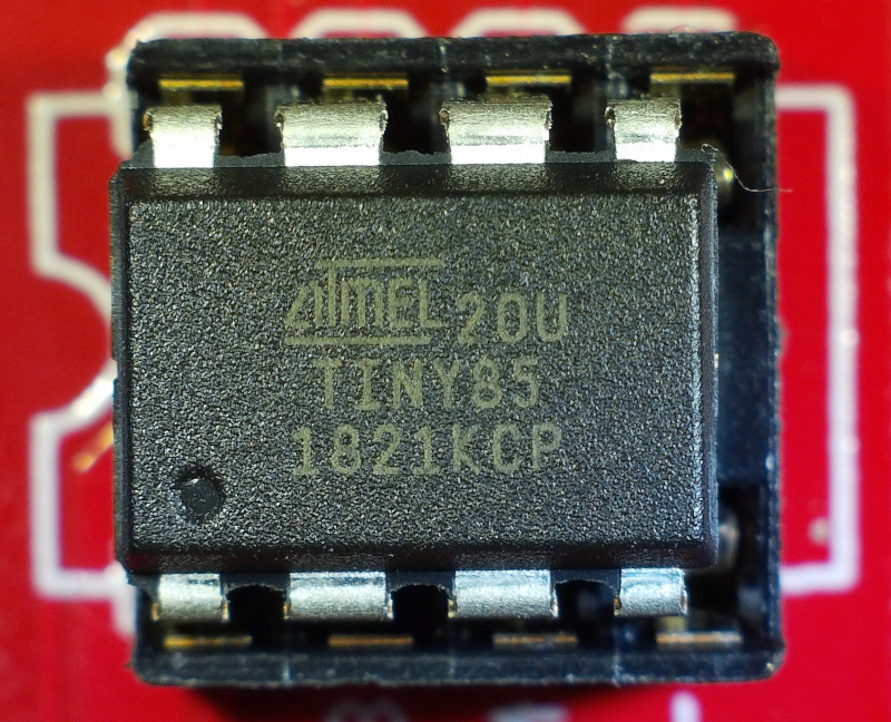
The Atmel ATtiny85 is capable little 8-bit microcontroller that plays very well with the Arduino ecosystem. It also comes in a compact and maker-friendly 8-pin Dual Inline Package (DIP), operates on 5V, and costs less than the aforementioned two dollars – making it a great option for controlling some WS2812b RGB LEDs (aka “neopixels”.)
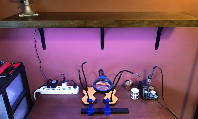
Since a true tinkerer can never have too much shelf space, I’m in the process of putting up some new shelves over my soldering station. “Off the shelf” shelves weren’t going to cut it, so I created a custom 42″x10″ poplar and maple set. There’s a 1-1/2″ lip all the way around to give them a feeling of substance – and to hide some lighting underneath.
While there are plenty of commercial lighting systems available, I wanted something with more of a maker flair – without being a visible tangle of wires wrapped in electrical tape.
Materials
Controller
– ATtiny85, DIP 8 form factor or dev board such as 5V Trinket
– AC Adapter power supply: 5V DC 2.5A, with 5.5mm x 2.1mm barrel connector
– Barrel jack, 5.5mm x 2.1mm (match the power supply connector)
– Breadboard or protoboard (1/4 size works well)
– (2) momentary buttons (Reset/Off, Mode Select)
– LED status light (3mm or 5mm)
– 330 Ohm 1/4 watt resistor (current limiter for LED)
– 100uF electrolytic capacitor
– 10nF ceramic capacitor
Optional
– 8-pin IC socket (strongly suggested if using protoboard)
– JST SM 3 pin male plug (for LED strip)
– Sparkfun Tiny Programmer (makes dealing with ATtiny85 much simpler)
https://learn.sparkfun.com/tutorials/tiny-avr-programmer-hookup-guide
Lights
– WS2812b strip 1m, 60 RGB LEDs (aka Neopixels)
– LED aluminum U channel with plastic cover, 1m
– (3) 3/8″ Flathead wood screws for mounting the U channel
Shelves
– 8′ x 10″ x 3/4″ board
– 12′ of 1-1/2 x 3/4″ trim boards
– Shelf brackets
– Mounting screws / drywall anchors
Schematic
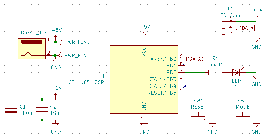
The design and power supply is based on an LED strip with 60 lights or so. A rough rule of thumb for WS2812 LED power consumption is to use 50mA per LED @ full white brightness. The sketch is set to use 50% brightness by default. With 60 LEDs during testing, it never peaked over 1.5A draw. Select your power supply max current accordingly based on the desired # of LEDs and max brightness.
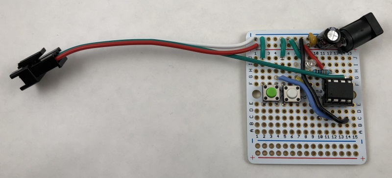
Breadboard
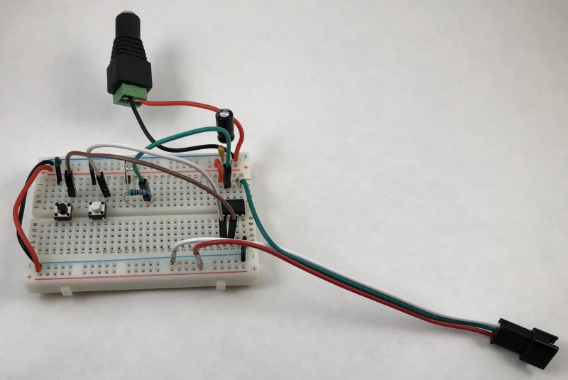
For testing breadboard setups, I usually just feed it power from a benchtop power supply. However, once I’ve established the power draw, I like to use a screw terminal barrel jack as shown to connect with the actual intended 5V power supply. Power-up/line noise issues may be present with the wall-wart that you don’t see with the benchtop PSU, so testing it before you create a protoboard is highly recommended.
Place the capacitors as close to the current source as possible to smooth out ripple and any sudden current spikes/drops. There’s no reverse-polarity protection included, so always check your connections before applying power.
Using momentary buttons with different colors makes it easier to differentiate the Reset button from the Mode button.
The status LED can be omitted, but it comes in handy to determine if the board is functioning correctly.
Controller Sketch
The sketch for the ATtiny85 uses the Adafruit NeoPixel library to control the WS2812 LEDs and some simple logic to cycle through the display modes when the Mode button is pressed and then released.
LED Display Modes
- LEDS_OFF: all lights off, Default on startup or reset
- LEDS_SOLID_WHITE: all lights on, solid white
- LEDS_SOLID_RED: all lights on, solid red
- LEDS_SOLID_GREEN: all lights on, solid green
- LEDS_SOLID_BLUE: all lights on, solid blue
- LEDS_SOLID_COLOR_CYCLE: : all lights on, slowly cycles through all colors
- LEDS_CHASE_WHITE: movie theater marquee effect, white lights
- LEDS_CHASE_COLOR_CYCLE: movie theater marquee effect, slowly cycles through all colors
- LEDS_RAINBOW: classic rainbow color effect
- LEDS_RAINBOW_CYCLE: uniform color distribution rainbow effect
Adding additional modes is simply a matter of adding it to the led_pattern_type enum, the led_pattern switch statement, and possibly creating a new method for it.
Setting Up the Arduino IDE
- Install the Adafruit NeoPixel library (Sketch -> Include Library -> Manage Libraries)
- Under File -> Preferences -> Additional Boards Manager URLs, add:https://raw.githubusercontent.com/damellis/attiny/ide-1.6.x-boards-manager/package_damellis_attiny_index.json
- Under Tools -> Board -> Board Manager, install the “atttiny” boards by David A. Mellis (thanks David!)
- Load the “attiny85-ws2812b” sketch
- Place the the ATtiny85 in the programmer and hook up to your computer
- Under Tools -> Board, select “ATtiny25/45/85“
- Under Tools -> Processor, select “ATtiny85“
- Under Tools -> Clock, select “Internal 16 MHz“
- Under Tools -> Programmer, select “USBtinyISP“
- Tools -> Burn BootloaderThis step is not always required, but if the ATtiny did not have a bootloader installed you won’t be able to upload a sketch. If the bootloader is present, but for a different clock speed, the LED strip lights won’t work because the timing requirements will be off. If the status LED stays on for longer than 250ms on startup/reset, the bootloader clock speed is probably wrong or your power supply voltage is too low.
- Sketch -> Upload
Protoboard
This project fits perfectly on a 1/4 size protoboard, but could be easily adjusted for a narrower profile if desired. I like using the JST connector for the LED strip, but you can also solder the LED leads directly to the board.
If using a DIP socket, make sure the notch on the socket and the dot indicating pin 1 on the ATtiny85 are on the same end. As a general rule, never use the labeling on any IC to indicate proper orientation. Pay attention to the dot!
I found that the “breadboard-friendly” barrel jacks require mounting at roughly a 45 degree angle on standard 2.54mm boards. Double-check the polarity of your power supply plug and the pins on the jack with a multimeter before soldering and/or frying the microcontroller.
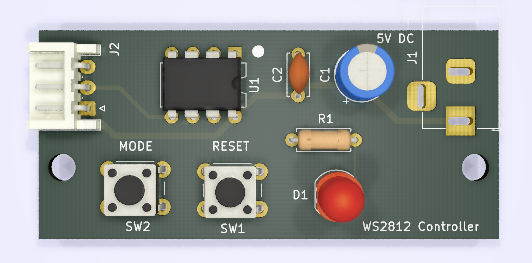
PCB
The PCB version is slightly more compact than a 1/4 protoboard, measuring in at 55mm x 25mm. Gerber files are available in the GitHub repo.
Future Modifications
The original version of this board included an infra-red receiver, but even after significant trimming the sketch exceeded the memory capacity of the ATtiny85. I’ll cover the IR-controlled version targeting the bigger and beefier ATmega328P MCU in a future post.