Once you are comfortable with the basics of surface mount soldering, it’s time to start using SMDs in an actual project. A great way to do this is to create your own breakout boards. Many breakout boards consist of a single SMT IC (i.e. analog to digital converter, amplifier, sensor, etc.), a few supporting passive components, and some header pins. The datasheets for these ICs often include a reference design for using the component. If you’ve ever bought a cheap breakout board off of eBay, chances are that its design is pretty much an exact implementation of the data sheet reference design and very little (if any) value-add engineering was applied.
If you can read a schematic and use a PCB design system such as KiCad, you can make your own breakout boards.
So why would you want to do this?
- It’s a great way to learn and hone circuit design and construction skills.
- Not all SMD parts have easily-obtainable breakout boards. Once you know how to roll your own, you never have to worry about this limitation ever again.
- The SMD chips are more plentiful and less likely to be out-of-stock than the breakout boards. Big companies don’t buy a lot breakout boards. They do tend to buy tens of thousands of components though, so the distributors tend to have lots of these on hand. As COVID-19 showed us, disruptions to the global supply chain are something you need to consider when sourcing your materials.
- Even if breakout boards are available, they may not be in a form factor that you want or be missing features that you need. Being able to tailor the board to your exact needs and specifications is a great option.
- With the advent of maker-friendly sales outlets such as Tindie, Kickstarter, and CrowdSupply, it’s never been easier to manufacture and sell your technological creations and possibly make some money.
- Because you can – and it’s fun.
For your first breakout, I suggest using a part that you already have some experience with. Having a known-working application just helps to eliminate a potential source of problems and simplifies troubleshooting.
The part should be relatively inexpensive, even in the low quantities that you’ll be buying. Even if you only plan to make one of the breakouts – always order a few extras in case of a faulty part, breakage, or loss.
The part should also have low or modest requirements in terms of additional components that it needs in order to function correctly. Remember the KISS rule.
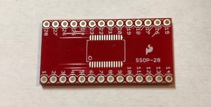
If the part has a common footprint, you might be able to find a simple pre-made bare breakout board for it. For example, the board below is from SparkFun for an SSOP-28 package part.
Most PCB fabrication services also provide a library of breakout boards that their customers have made that your can use to order your own. Just make sure that the footprint matches the one you plan to use, as many parts are available in multiple package formats.
Finally, it’s pretty easy to whip up your own basic breakout in any PCB design tool, such as KiCad. Since these are almost always small, 2-layer boards, you can generally get them fabricated very cheaply (i.e. $1 each in quantities of 5 or more.) For a quick rundown of working with KiCad, see Creating Your First Printed Circuit Board .
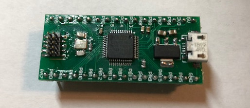
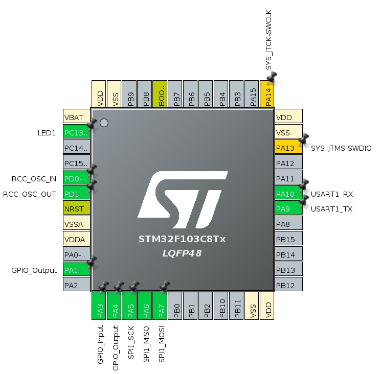
One of the first breakouts that I made was for the STM32F103C8T6 – the same microcontroller that is used in the “Blue Pill” Arduino board. It’s a 32-bit controller running at a max speed of 72MHz, with 64K of Flash, 20K of SRAM, and a nice assortment of timers and peripherals.
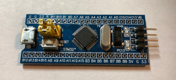
At a street price of about $2 each, these little boards provide some great bang for the buck. There’s a relatively small number of parts that are needed to produce a functional setup. The part count can be reduced even further though if you’re willing to forego a few features.
For example, the large silver 8MHz and black squarish 32.767KHz external oscillators are only required if you want to use the highest CPU clock frequency, USB, and/or the Real Time Clock. If your application doesn’t need these things, you can potentially reduce the power consumption, size, and number of potential failure points by eliminating these parts. Same for the two LEDs on the board.
The STM32F103C8T6 breakout shown below is is as simple as a breakout gets – just the controller and some header pins. However, it allows you to easily verify that your solder job was successful. It also allows you to swap out different supporting components (i.e. different external oscillators)
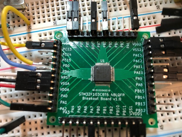
The square form factor of the board means that the breakout pins are in the exact same order and relative position as the physical pins on the board. This make it very easy to compare the electronic configuration with the physical implementation.
Once you have the bread-boarded prototype working, then it’s time to translate to the final design. We’ll take a closer look at what that looks like, along with the board programming and validation process in the coming posts.